
Useful Links
slot racing products
www.mackslotracing.co.uk
Piano wire for spine and rail hinges (032 as a starting size, but whatever works best)
Good quality solder and flux
Cut all parts off, trim tab on joint of rails, and cut through tab at rear of pans.
Make sure everything is flat, and clean.
MAKE SURE IT’S THE RIGHT WAY UP
There is a choice of pillow blocks; one is fixed height and one air adjustable.
Trim either bottom leg of gear side pillow block or cut end out of slot in motor brace.
Slot pillow blocks into motor box, push into main chassis, check all is square and then solder.
Now slot guide plate locating tab into centre section, push guide tab spacer plate, and guide tab in place, if you want to use the guide saver, now push this in place, and solder.
If you don’t use the guide saver, trim the tabs flush with the top of the guide tab.
Decide what size spine is to be used and open out holes and slot if necessary.
Bend the end of the wire at 90 degrees and trim to length so it just locates into the hole in the motor box and into the slot in the guide plate.
Slide spine lead wire guides onto spine, fit in place and solder guides and ends of spine in place.
Solder rail hinge tubes in place, and then carefully solder wire hinges into the rails .Make sure they do not solder to tubes .Steering can be adjusted by the amount of play in this joint.
Now solder the pan unstops and the pan hinge pins in place. Make sure these move nicely and don’t bind .You may have to bend the pans out slightly.
Now solder the rear pin tube and front pin tube mounts into place.
Decide if you want fixed pin tubes or floating ones .The rear pin tubes can be made floating by putting a retainer on each end of the pin tube on the inside of the mount.
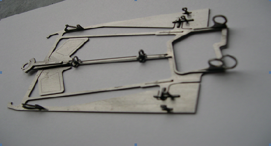
BUILDING INSTRUCTIONS GT 12 TAZER